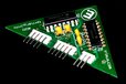
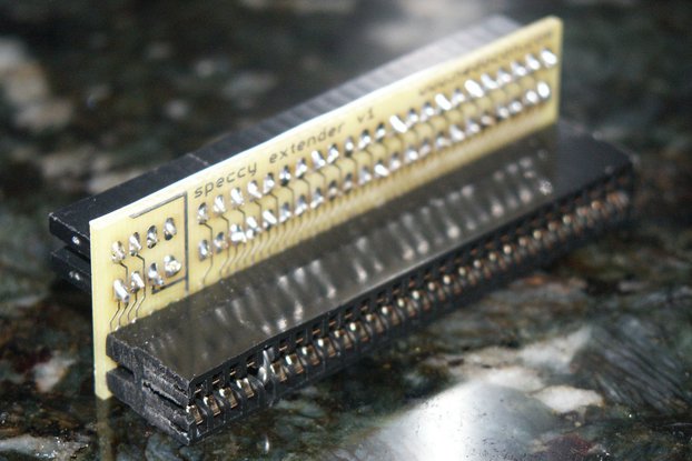
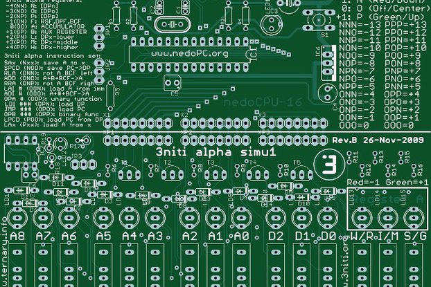
TRIMUX is basic component to build ternary computers where every signal may have one of 3 possible states: -1, 0, +1
Designed by Ternary Research Corp. in United States of America
Buy with confidence.
Our Tindie Guarantee protects your purchase from fraud. Learn More
TRIMUX - dual balanced ternary multiplexer/demultiplexer TRIMUX is basic component to build ternary hardware (including ternary computers). Positive voltage means +1 (P). Zero voltage means 0 (O). Ne…
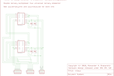
Read More…TRIMUX is basic component to build ternary hardware (including ternary computers). Positive voltage means +1 (P). Zero voltage means 0 (O). Negative voltage means -1 (N). Two power sources are required (+5 volts and -5 volts). This device consists of two independent multiplexers/demultiplexers and each of them may connect any of 3 inputs to 1 output based on control signal (connection may work in both directions - so it could be 3 outputs connected to 1 input). Switching frequency could be up to 1 MHz (see oscillograms).
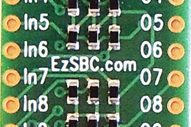
Connector JP1:
(1) S1 - select input of the 1st ternary multiplexer
(2) N1 - connected to C1 if S1=N ("negative" or -5V)
(3) O1 - connected to C1 if S1=O ("zero" or 0V)
(4) P1 - connected to C1 if S1=P ("positive" or +5V)
(5) C1 - common signal of the 1st ternary multiplexer
Connector JP2:
(1) S2 - select input of the 2nd ternary multiplexer
(2) N2 - connected to C2 if S2=N ("negative" or -5V)
(3) O2 - connected to C2 if S2=O ("zero" or 0V)
(4) P2 - connected to C2 if S2=P ("positive" or +5V)
(5) C2 - common signal of the 2nd ternary multiplexer
Connector JP3:
(1) V-NEG - negative voltage (typically -5V)
(2) GND - ground wire
(3) V-POS - positive voltage (typically +5V)
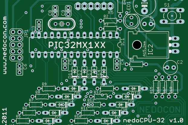
Bill of Materials:
IC1,IC2: DG403 (DIP16)
C1-C4: 0.1uF (tantalum)
JP1,JP2:right-angle 5-pin headers
JP3: right-angle 3-pin header
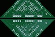
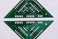
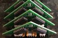
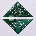
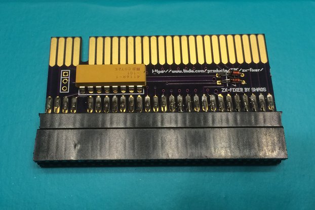
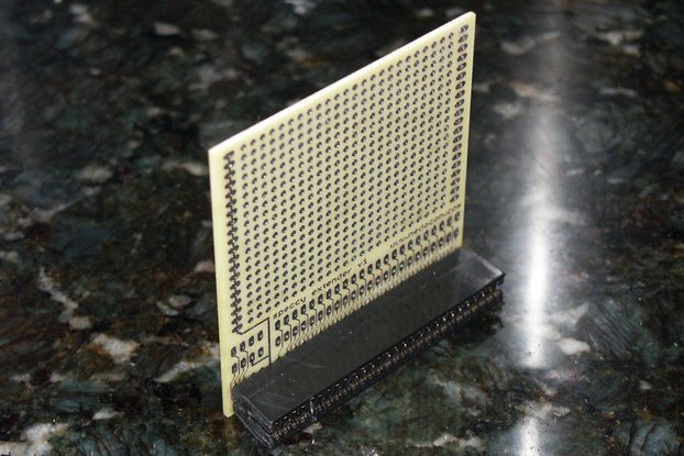
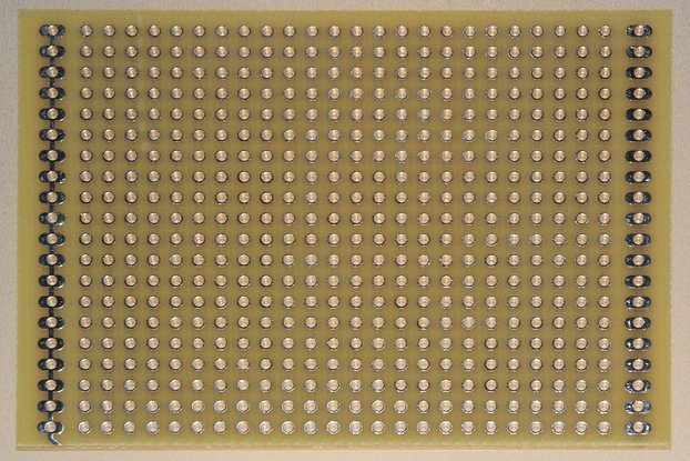
By default you will get bare PCB only:

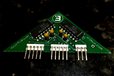
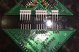
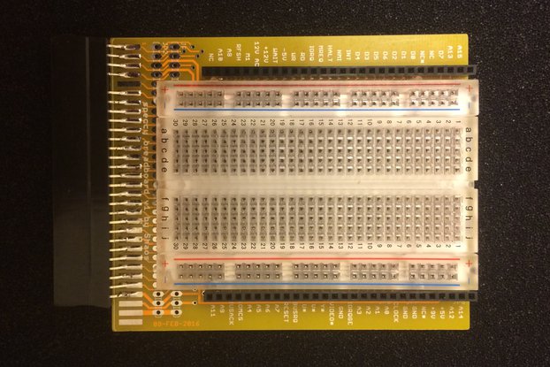
But you can choose options to have a KIT (PCB and set of components to solder TRIMUX) or even pre-assembled and fully tested board...
Buy with confidence.
Our Tindie Guarantee protects your purchase from fraud. Learn More
$7.95
$9.00
$10.00
$14.00
$13.00
$33.00
$19.00
$4.95
/i/72212/products/2016-07-18T04%3A51%3A55.873Z-trimux.jpg?1606306133)